Construction activities & Support2


CASE 1: Conductor with signs of stain or corrosion was installed (TX)

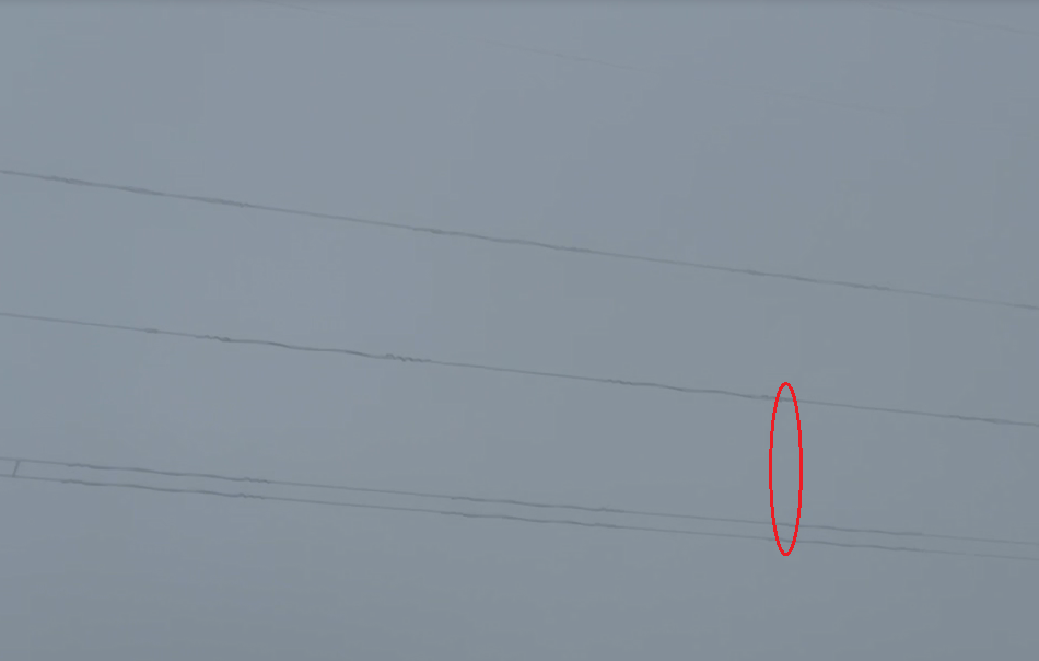
Issue: The contractor noticed some type of surface defect on the 1272kcmil ACSR Bittern conductor. Initially the subcontractor didn't say anything to anybody and went ahead to install the conductor. TLine FW345-TX

Solution: Southwire was contacted and confirmed a case of water staining. "When conductor reels are stored outdoors, water can accumulate on the conductor on the underside of the reel. If the water contains chemicals from the surrounded atmosphere, a black water stain can appear on the conductor. Water stains are a cosmetic issue; they have no adverse effect on the performance or service life of the conductor. In most environments, the conductor will darken in the first few months after the line is energized, and the stain will no longer be noticeable. Aluminum Association Technical Bulletin TR3, "Guidelines for Minimizing Water Staining of Aluminum" discusses this issue in detail and contains advice for avoiding water staining." 

In summary, while aesthetically displeasing, the stains will have no adverse effect on the conductor.


                     Amarillo-TX


CASE 2: Jumper arm installed incorrectly on the wrong side. (TX)

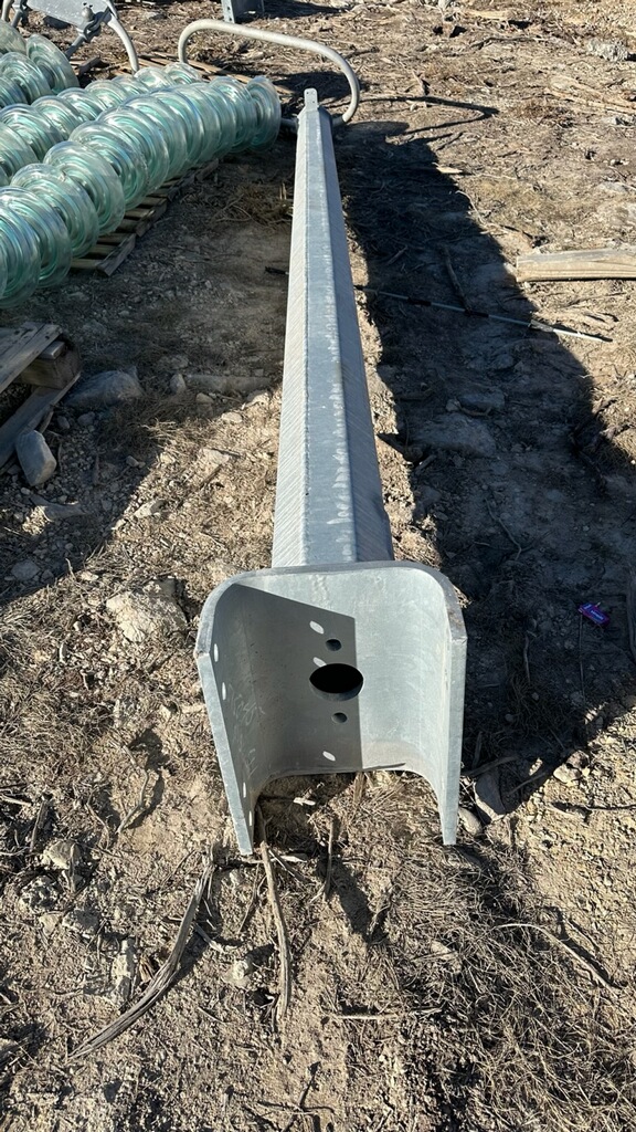
Issue: The contractor installed the steel jumper arms on the wrong side of the 345kV steel pole.
Review: It was noted as a design-manufacture error by the vendor, not captured during their QA/QC nor the consultant review/approval.

Solution:  Part of the external thru plate was cut and installed/welded on the opposite, right side of the pole. Schedule was a factor to resolve the issue quickly.
a.)Cut the thru plates off on the outside, 4.5" min from the edge. b.)Trim the cut part if necessary to the proper length, and double bevel the weld edges 45 degrees. c.)Remove the galvanizing coating from the butt ends of the thru plates. d.)Fit up the cut part to the thru plate butt ends, the bolt hole MUST be vertical inline and 3" from the shaft face. e.)After fitting up. weld up the cut parts to the thru plate butt ends. Clean the welded areas. f.)Touch up the welded areas with zinc rich paint per ASTM A780 requirement.


CASE 3: 345kV Steel Pole damaged while stringing conductors. (CO)

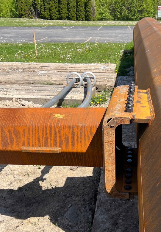
Issue: The top pole section, where the bracket attaches and is welded, was damaged/dented during the conductors stringing.
Solution: After a quick review with the manufacturer, the top section of the pole was decided to be replaced. Cost: $8,519+freight (Aug.2023)


CASE 4: Galloping occurrence on the new 345kV TLine (CO)

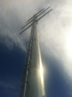
Issue: Outage occurred due to galloping effects on a new TLine a couple of months after energizing(Dec. 2023). Airflow Spoilers were already installed to avoid galloping on all East-West sections of the TLine where galloping was noted on another close in-service TLine.

Solution: It's under investigation. Possibly the whole line should have been considered to have airflow spoilers, not only the East-West sections.


Airflow spoilers installation (08.18.2023)


Construction activities & Support1

CASE 1: Conductor damaged during installation:

2x1033.5 kcmil, 54/7, ACSS MA2 Curlew, 35,000Lbs RBS

New 20miles, 345kV Tline, 2050 MVA, 140Ft ROW, IN


Solution: 

1.)Armor Rods=No 

2.)Sleeve repair=Yes, but not immediately available during construction

3.)Splice=Yes, available. Installed.


Result:


CASE 2: Arm deflection:

Issue: The 345kV arm installed on ground didn't show a 2deg. rise design deflection, it was 2" less than designed.

After the review with the manufacturer it was clear 1.) The arm was not manufactured following the design or 2.) Installation was not done properly. It, most probably, was 1.

Solution: After the analysis with the manufacturer it was shown that the missing deflection would Not affect the structure capability itself. The installed arm downward deflection was Not noticeable.


CASE 3: Conductor damaged during installation:

Issue: One of the lineman nicked the wire while hanging jerk ropes. 3 strands were broken and about 5 other were nicked up.

Solution: Armor rods were installed following the PLP repair manual table.


CASE 4: Foundation construction, water presence (345kV Weathered Steel pole, double circuit, double bundle conductor)

Issue: Unexpected water was encountered while drilling the foundation for a 345kV Steel Pole installation.

Solution: Drill an oversized shaft with the use of temporary casing and drilling under water with slurry products. The pole base is 7'-9" in diameter. Contractor looked to drill a 13' diameter shaft down to 45'. The contractor poured concrete via tremie method to fill the shaft. Once the concrete has set-up, contractor drilled drilled through the concrete with a 9' tool to give the pole base 6" of clearance all the way around. Contractor drilled down to 40' leaving at a 5' of concrete below the pole base. Contractor then set the pole base maintaining plumb and twist and backfill with stone and concrete.

This new procedure took place at a new location. 

Notes: -After the review of the geotech report and foundation design, it was determined that the plug within the CMP and lack of concrete backfill around the CMP caused the CMP with plug to float. The new procedure for installation focused to ensure the backfill around the CMP is complete and set prior to pole installation.

-For the hole and CMP that remained at the existing drilled foundation, the contractor was ordered to review if CMP can be removed and hole salvaged. The concrete cured to the CMP  removal is challenging. Contractor was asked to review if there are appropriate means & methods to remove concrete from the CMP, clean out the hole and reset the plug and structure. On the other hand for the hole abandoning option contractor was requested to backfill hole to ensure all voids are filled, including the floated CMP.


PYRAMAX TYPE TUBULAR STRUCTURES 

Some transmission lines require very long span crossings over rivers and other obstacles. The increased height and heavy loading may make lattice towers and tubular H-frames inefficient designs for these structures.

1.Structure Concept-Configuration:


A tubular frame may look like a lattice tower or pipe leg tower, but the quantity of members is much less which reduces installation labor and erection time. Additionally, the four legs connected with cross braces convert external loading to large axial force and avoid large bending moment at the base.

2.Design and Analysis:

-The design of tubular 3D frames performed by Valmont follows the ASCE 48 Standard ‘Design of Steel Transmission Pole Structures’.

-The grades and types of steel used for 3D frames are the same as for transmission poles.

-The extreme wind load cases should include wind in several directions – transverse, longitudinal and diagonal.

-An in-house Valmont's program for tubular structures has been enhanced to process the increased complexity of tall 3D frames. The goals of design optimization are to minimize bending moments at base of the legs and to minimize total structure cost. 

-The tubular 3D frames are much more rigid than single poles in both transverse and longitudinal directions. Deflections in tubular 3D frames as a percentage of structure height are much smaller. Even under the maximum design load, deflection at top of these frames is typically between 2% and 3% of the structure height.


ANSYS Validation:

ANSYS is like an MRI, which scans and produces more detail and depth into the target areas to make sure nothing is overlooked. ANSYS provides a rich graphics capability that can be used to display analysis results on a very high-resolution graphics workstation.


3.Use:

-For very long span crossings over rivers and other obstacles.

-In the United States, tubular 3D transmission frames have been used in limited applications in the past. In many high voltage substations, deadend A-frames are installed but they are not tall. In China, pipe leg lattice towers are used in 1000-kV ultra-high voltage transmission lines replacing angle legs with round tubular members to increase loading capacity. In the US and Japan, pipe leg lattice towers are also used for some telecommunication structures.

4.Tests:

- A full-scale loading test was performed. Six load cases were selected by the customer and Valmont engineers for the test: one extreme wind, one deflection limit and four broken wire cases.

-The broken wire condition is at one shield wire plus one conductor point or at two conductor points. The transverse and vertical loads were applied at two shield wire points and six conductor points. Longitudinal loads were applied at the shield wire and conductor points where broken wire conditions occur. The wind load on the frame itself was converted into concentrated transverse forces at the top and bottom of the right columns.

 5.Results:

-The 3D test frame passed 100% loading in all six load cases without failure or permanent deformation in any member or connection. After loading was removed, the structure came back to about 1 in. from the original position. Deflections met customer specified limit and were close to calculated values. After the structure was disassembled, post-test inspection confirmed everything was in good condition.

6.Conclusions:

  • The design process of tubular 3D frames have undergone comprehensive static analysis, ANSYS FEA validation and full scale loading test.
  • Tubular 3D frames have been successfully installed and put in operation for US and international customers. àValmont did not mention what Clients or places installed.


********************* *|* *********************


500kV AC Transmission Lines

It's always interesting and fulfilling getting involved in the Engineering preparation of 500kV TLines and higher voltage levels (765kV in the USA).

Routing/Siting preparation, TLines design criteria, Electromagenic Field and Electric Field study, radio frequency and Corona effects, conductor optimization analysis and selection, structures optimization analysis and selection, conductor thermal calculation, regulators input, real estate, environmental, line survey, permitting (FAA, railroad), plscadd modeling, line layout, plan and profile dwgs., boring locations, permit documents, phasing drawings, thermal rating verification, stringing charts, structures design, loading tree, configuration dwgs, structures procurement, vendor's calculation and dwgs. review/approval. Bill of materials and materials selection, specifications, Geotech report, foundation design and drawings, engineering drawings, construction specifications, Issue for construction package release, engineering construction support, As-built package, close out.

Some projects I've participated on:
500kV Heartland to Ellerslie. Alberta-Canada. Design engineer.
500kV Charrua-Ancoa. Chile. OE
500kV Colectora-Cuestecitas-Las Lomas. Colombia. OE
500kV Cirebon 2 to Gitet Mandirancan. OE